P4946 Current Calculation
Background
NOIP 2018 original mock problem T7.
NOIP 2018 original mock contest DAY 2 T2.
Difficulty: NOIP DAY 1 T2 or DAY 2 T2.
For related electrical knowledge, please refer to “Background Knowledge” in the “Hint” section.
Description
After looking at a complex circuit diagram, you find that the number of circuit components studied in junior and senior high school is relatively small. Therefore, you want to design a program to analyze circuit diagrams with more components and perform some calculations.
After long thinking, you finally found a way to describe a circuit diagram:
1. A circuit diagram can be represented by a connected graph with $n$ nodes and $m$ undirected edges, where $n$ represents wire junctions, $m$ represents the number of components, and the circuit components are only power sources and resistors.
2. The graph has no self-loops, but it may have multiple edges.
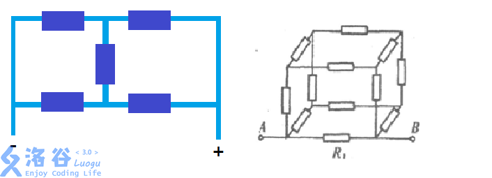
3. The most complex case of the circuit is **series connections nested inside parallel connections**, and **no more complex circuits** will appear. For example, the following cases will not appear:
For example, Sample 1 is a circuit diagram that satisfies the conditions (see the picture in the explanation of Sample 1).
Since this is your first attempt, you decide that the circuit contains only power sources and resistors, and you decide to compute the maximum current and the minimum current in the circuit.
After sorting out your ideas, you decide to start trying.
Input Format
There are $m+1$ lines in total.
The first line contains two numbers $n,m$, meaning the circuit diagram is abstracted as an undirected graph with $n$ nodes and $m$ edges.
In the next $m$ lines, for each line:
The first two numbers are $x,y$, meaning there is a component between $x$ and $y$.
Then there is a character: if it is $'P'$ it means a power source, and the direction from $x$ to $y$ is from the negative terminal to the positive terminal; if it is $'R'$ it means a resistor (without quotes).
Then there is a number: if it is a power source, it indicates the voltage (unit: volt); otherwise it indicates the resistance (unit: ohm).
Output Format
Two lines.
The first line outputs the maximum current value, keeping two decimal places.
The second line outputs the minimum current value, keeping two decimal places.
Explanation/Hint
**Background Knowledge:**
Ohm’s law: $I=\frac{U}{R}$, where $I$ is current, $U$ is voltage, and $R$ is resistance.
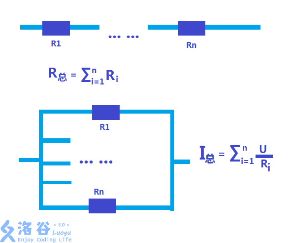
Series connection: in a series circuit, currents are equal, and the total resistance equals the sum of the resistances.
Parallel connection: in a parallel circuit, voltages are equal.
Series-parallel: a combination of series and parallel.
**Explanation of Sample 1:**
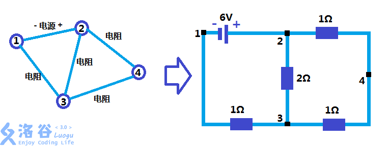
As shown, the equivalent resistance of all resistors is $2Ω$, so the maximum current is $\frac{6V}{2Ω}=3A$. In branch $2-3$ or $2-4-3$, the current is $1.5A$, which is the minimum current.
**Hints for Sample 2/3:**
In Sample 2, the equivalent resistance of all resistors is $\frac{6}{11}Ω$, and the minimum current is on branch $1-4-3$. In Sample 3, the equivalent resistance of all resistors is $18Ω$.
**Constraints:**
For $30\%$ of the testdata: $n,m